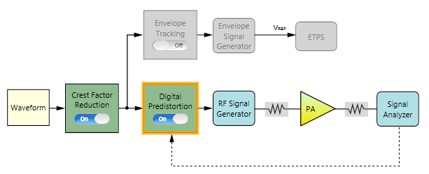
The following figure shows the block view settings in N7614C for DPD measurement. In this example, the Envelope Tracking block is turned Off.

The remaining section of this topic provides an example procedure of setting N7614C for DPD measurement. Note that for different PA, the settings are different.
Step 1: Set the Waveform Block
Step 2: Set the Crest Factor Reduction Block
Step 3: Set the Digital Predistortion Block
Step 4: Set the RF Signal Generator Block
Step 6: Set the Signal Analyzer Block
Step 7: Set the Measurement View
Click on the Waveform block icon on the UI. In the right panel, do the following:
Select Preloaded as the Waveform Type and select the "LTE_FDD_5M_QPSK_FullRB.wfm" file.
Set the Bandwidth to 5 MHz according to the waveform bandwidth.
Set the Resampling Ratio to 3.
![]()
Set the CFR Algorithm to Peak Windowing. Refer to CFR Concept for details about the two different CFR algorithm.
Set the Target PAPR to 7 dB.
![]()
Set Reference (w/o DPD) to On.
Set the PA Model Type to Look-up Table. Refer to DPD Concept for details about different PA model types.
Set the LUT Type to Absolute and LUT Apply Mode to AM/AM, then AM/PM.
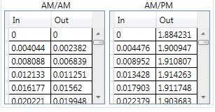
Enter the look-up table as below or you can also use an existing look-up table.Below is an example of the look-up table used here.
In the process of measurement, you can also select another look-up table and click the Apply button  . This look-up table will be applied to the waveform under test directly.

Click on the RF Signal Generator block icon on the UI. In the right panel, do the following:

Set Frequency to 5.18 GHz.
Click on the PA block icon on the UI. In the right panel, do the following:
Enter the PA information by setting the Loss In, Loss Out, and PA Gain.
Select PA Output as the Power Mode and set Power Servo to On.
Set Power to 17.00 dBm and Power Tolerance to 1 dB. This is to set the output power of the PA and the accuracy of the power servo.
The initial Amplitude setting in RF Signal Generator block will be set to (Power - PA Gain + Loss In) automatically.
Click on the Signal Analyzer block icon on the UI. In the right panel, do the following:

Note that the Frequency value is coupled to the frequency setting in RF Signal Generator block.
Set the Trigger Source to External 1 and adjust Trigger Delay value as needed. For most cases, you can use the default value.
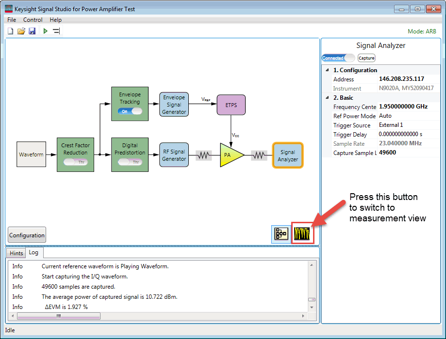
 button on the

You can turn Intermediate Result to On and set the ACP parameters as required. In this example, the default settings are used.